

Repmold is a term that’s been popping up in prototyping and tooling discussions. However, it isn’t a registered trademark, a single company, or a formally standardized industry process. It’s an informal shorthand — a blend of “replicate” and “mold” — used to describe a digital-first approach to making, repairing, or replicating molds. It uses 3D scanning, CAD, and 3D printing instead of relying only on conventional machining.
Because repmold doesn’t have one fixed, universally agreed definition, different sources describe it slightly differently. This guide takes the most consistent and technically grounded version of that definition and covers it in depth — including where it fits against traditional molding, what it’s realistically good for, and where it falls short.
If you’re evaluating this approach as an option for a project, here’s what actually matters before you commit to it.
It’s worth being upfront about why the definition varies so much depending on where you look. A handful of manufacturing blogs have published explainer content on this word over the past year, and they don’t fully agree with each other — some frame it as a manufacturing process, others describe it more like a digital platform or service. None of them trace it back to a single company, patent, or standards body. That’s a useful thing to know before treating any one source, including this one, as the final word on what the term means. What follows is the most technically consistent and widely echoed version of the definition, built from how the underlying techniques — 3D scanning, CAD cleanup, additive manufacturing, and casting — actually work in practice.
1. What Repmold Actually Means
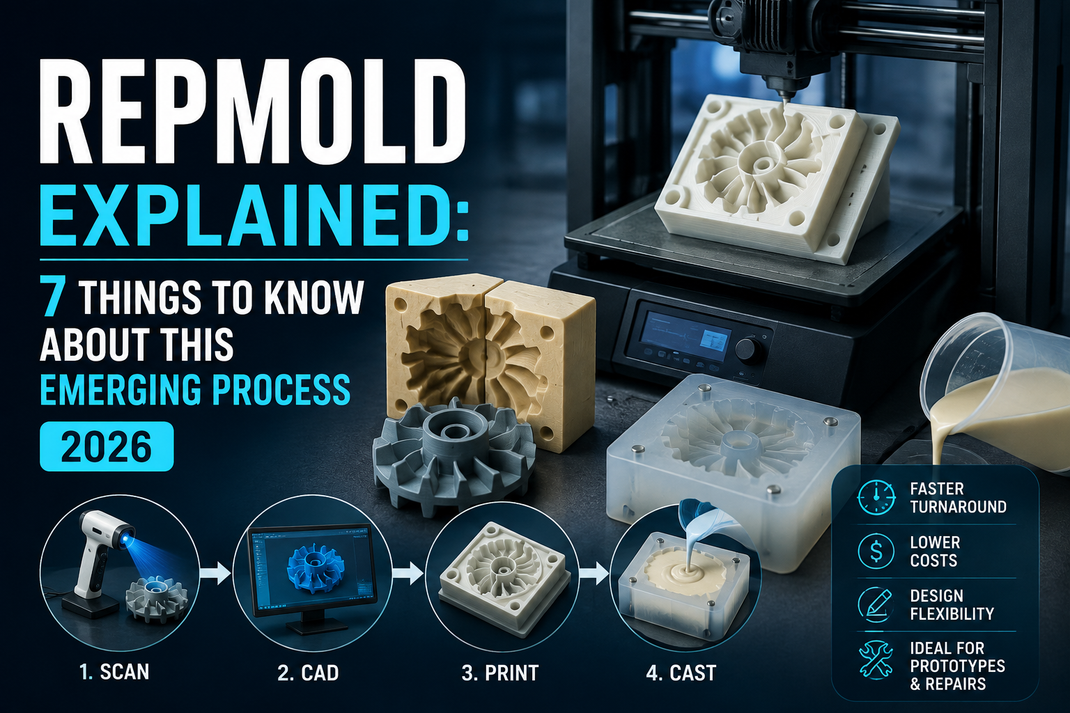
At its core, repmold technology describes a workflow. First, you scan or model a part digitally. Next, you clean up that model in CAD software. Finally, 3D printing produces the mold directly or creates a pattern for casting one in silicone, resin, or another material.
The name itself signals its two most common uses — replicating a mold that no longer exists and repairing one that’s worn or damaged. It isn’t one single fixed process. Since it’s a community-driven term rather than a standardized one, manufacturers, hobbyists, and writers may use it differently.
2. Repmold Process Explained Step by Step
The general repmold process explained in practical terms looks like this:
- Capture the geometry. A technician either 3D-scans an existing part or mold, or builds the shape from scratch in CAD software.
- Clean and convert the model. The raw scan or CAD file is corrected for errors, gaps, and noise, then converted into a mold cavity — the digital inverse of the part’s shape.
- Produce the mold. The mold is either 3D-printed directly, or the printed model is used as a master pattern for casting a mold in RTV silicone, resin, or a castable metal.
- Cast or mold the part. The finished mold produces test parts through injection molding, resin casting, or vacuum forming.
Each step matters more than it might look. Skipping the cleanup stage is one of the most common points of failure — raw scan data almost always contains noise that needs manual correction before it’s usable as an accurate mold cavity.
3. Repmold vs Traditional Molding
Understanding repmold vs traditional molding comes down to trade-offs between speed, cost, and durability rather than one approach being universally better.
| Factor | Traditional Mold Making | Repmold-Style Process |
| Typical lead time | Weeks to months | Days to a couple of weeks |
| Upfront cost | High — machined steel or aluminum tooling | Lower — digital tools plus printing materials |
| Best suited for | Large production runs | Prototypes, short runs, repairs |
| Design flexibility | Costly to change once tooling is cut | Easy to revise the digital model |
| Mold durability | Very high, built for thousands of cycles | Moderate, depends on the print material used |
| Skill and equipment needed | CNC machining, mold-making expertise | 3D scanner, CAD software, 3D printer |
Traditional steel or aluminum tooling still wins on durability and per-unit cost at high volumes — that hasn’t changed. Where a digital, repmold-style approach earns its place is in the gap traditional tooling handles poorly: fast iteration, low-volume runs, and emergency repairs where waiting weeks for machined tooling isn’t an option.
4. Where Repmold Fits: Industry Applications
The realistic use cases for this approach cluster around situations where speed or design flexibility matters more than long-term durability.
Repmold for Medical Devices
Repmold for medical devices applications tend to focus on early-stage prototyping — testing housing shapes, ergonomic grips, or enclosure fit before committing to production-grade tooling, which is especially valuable given how often medical device designs go through multiple regulatory-driven revisions.
Repmold Automotive Parts
Repmold automotive parts use cases are common in the aftermarket and restoration space. A shop restoring an older vehicle can scan a discontinued trim piece and produce a small batch of replacements instead of tracking down an original mold that may no longer exist anywhere.
Repmold Aerospace Components
For repmold aerospace components, the appeal is mainly in low-volume, highly specific part replication — jigs, fixtures, and non-structural housings where a full certified production tooling run isn’t justified for the quantities needed.
Repmold Electronics Housing
Repmold electronics housing projects are one of the more accessible entry points, since consumer electronics enclosures are often simple enough geometrically to print or cast reliably without extensive post-processing.
5. Low-Volume Manufacturing Solutions
This approach is best understood as one of several low-volume manufacturing solutions, alongside options like CNC-machined short-run tooling or direct 3D-printed end parts. What sets a repmold-style workflow apart is that it specifically targets mold and tooling replication — not just producing individual parts, but recreating the tooling itself digitally.
For businesses that need somewhere between a handful of units and a few hundred, this middle ground avoids both the high upfront tooling cost of full production molds and the per-unit cost ceiling of one-off 3D-printed parts.
6. Custom Part Replication: The Core Value
Custom part replication is arguably the single most practical use case, particularly for discontinued or one-off parts. Scanning an existing physical object and reverse-engineering it into a usable mold cavity solves a specific, recurring problem: what to do when the original tooling, CAD files, or manufacturer no longer exist.
This matters most to three groups:
- Product designers iterating on a part shape multiple times before committing to expensive production tooling
- Maintenance teams needing a fast replacement for broken tooling without weeks of downtime
- Small manufacturers and startups who can’t justify traditional tooling costs for short production runs
7. Common Mistakes and Realistic Limitations
A repmold-style workflow isn’t a universal replacement for conventional tooling, and treating it as one leads to predictable problems:
- Skipping post-scan cleanup. Raw scan data almost always needs manual correction before it functions as an accurate mold cavity.
- Choosing the wrong print material. Not every 3D-printed resin or filament withstands injection-molding temperatures or repeated casting cycles — material selection matters as much as geometry.
- Underestimating shrinkage and tolerances. Printed molds can behave differently from machined ones as materials cool or cure; test parts should be checked against tolerances before a full run.
- Assuming it scales to high volume. For tens of thousands of identical parts, conventional steel tooling remains superior on both durability and long-term per-unit cost.
Materials Commonly Used in This Workflow
The material choice at each stage affects the outcome as much as the process itself.
Rigid photopolymer resins are common for the printed mold or pattern because they offer a smooth surface finish and capture fine details. Engineering-grade filaments like nylon or polycarbonate hold up better under repeated thermal cycling. These are useful when the mold itself needs to be reused many times.
For cast molds, RTV (room-temperature vulcanizing) silicone remains the most widely used option. It’s flexible enough to release parts with moderate undercuts without damaging the mold or the part. Depending on the casting material, it can tolerate dozens to a few hundred casting cycles.
Polyurethane resins are common for final cast parts used in functional prototypes. They can be formulated to mimic the mechanical properties of production plastics like ABS or polypropylene. This lets teams test fit and function before committing to injection-grade material.
How This Compares to Other Rapid Tooling Options
This isn’t the only route to faster tooling — it’s worth knowing how it stacks up against the other common alternatives before assuming it’s the right fit.
Direct 3D-printed end parts skip mold-making entirely. Instead, they print the final part itself. This works well for very low quantities, such as a handful of units. However, it becomes slower and more expensive per unit once you need more than a few dozen identical pieces. Each part must be printed individually rather than cast in batches.
CNC-machined short-run tooling sits between the two. It costs more upfront than a printed or cast mold but produces a more durable tool capable of higher cycle counts — a reasonable middle ground when a project needs a few hundred to a few thousand units and a printed mold won’t hold up that long.
Soft tooling services offered by some manufacturing bureaus follow a broadly similar workflow to what’s described here, but as a paid service rather than an in-house process — useful if a team doesn’t want to invest in its own scanner and printer.
Choosing between these options comes down to three questions: how many units are actually needed, how much geometric complexity the part has, and whether the team already owns the equipment or needs to outsource it.
What to Check Before Starting a Project
A few practical questions can help determine whether this approach is a good fit. Answering them before starting can save time and materials:
- What’s the actual production volume? Under a few hundred units generally favors a digital, printed-mold approach. Above that, traditional tooling usually pays for itself.
- What tolerances does the part require? Tight tolerances, especially on mating or sealing surfaces, may require machined tooling regardless of volume.
- What material will the final part be made from? The mold and process must be compatible with the intended casting or molding material. Not every combination works.
- Is the part geometry simple or complex? Undercuts, thin walls, and fine surface details all affect how well a scanned-and-printed mold performs compared to a machined one.
Answering these upfront avoids the most common failure mode: committing to a fast, low-cost process only to discover partway through that the part’s requirements needed traditional tooling all along.
A Realistic Starting Checklist
For teams considering trying this workflow for the first time, a small pilot run tends to work better than committing a full project to it immediately:
- Start with a simple, low-complexity part to validate the scan-to-mold pipeline before attempting anything with tight tolerances or fine surface detail.
- Budget for at least one iteration of the mold — first attempts rarely produce a perfect cavity on the first try.
- Test the finished part against real tolerance and fit requirements before scaling up to a full production batch.
- Keep the original digital files (scan data and cleaned CAD model) even after the mold is produced, since they make repeating or repairing the mold far faster the next time around.
Treating the first attempt as a validation step rather than a finished production process tends to produce better long-term results than trying to scale immediately.
Is This Worth It in 2026?
It depends entirely on volume and purpose. For prototyping, low-volume production, or urgent repairs, this approach can save real time and cost compared to waiting on machined tooling. For high-volume production, traditional tooling still wins — no digital shortcut currently changes that math.
The honest takeaway is that this is a useful technique for a specific set of situations, not a wholesale replacement for conventional mold making. Anyone evaluating it should weigh their actual production volume and durability requirements before choosing between the two.
Frequently Asked Questions
Is repmold a specific product or company?
No. Repmold is an informal, descriptive term for a process combining 3D scanning, CAD modeling, and 3D printing to make or repair molds — not a single branded product, patent, or company.
Can repmold replace injection molding entirely?
Not for high-volume production. This style of process is generally better suited to prototypes, repairs, and short runs, while conventional steel or aluminum tooling still performs better at large production volumes.
What equipment is needed to try a repmold-style workflow?
At minimum: a 3D scanner (or CAD modeling skills), design software to clean up and convert the scan into a mold cavity, and access to a 3D printer capable of producing the mold or a pattern for casting.
How long does the process take compared to traditional tooling?
A repmold-style mold can often be produced in days rather than the weeks or months typical of machined production tooling, though exact timelines depend on part complexity and the printer or materials used.
Is this approach suitable for repairing damaged industrial molds?
Yes — repairing worn or damaged molds by scanning the original geometry and reproducing a corrected version is one of the two most common uses of the term, alongside replication of molds that no longer exist.